

FANUC | Introduction to the Startup Inspection of the Spraying Robot
Release time:
2025-07-08 17:08
Source:
FANUC | Introduction to the Startup Inspection of the Spraying Robot
1. Definition
The robot power-on check mainly includes the hardware inspection of the control cabinet and the robot body to confirm that there is no abnormality in the equipment and ensure that the equipment is in a state that can be debugged normally.
2. Preparation for work
Electrician screwdriver, diagonal pliers, multimeter, some short wiring, electrical tape, debugging U disk (2G is best) or MC card and card reader, computer.
3. Required skills
Electrician's certificate
4. Brief description of the scene
The robot power-on is a key node in the on-site installation and commissioning plan, and the installed robot needs to be powered on for testing, the purpose of which is to check the robot hardware damage and abnormal alarm that may be caused by long-distance transportation and on-site installation and construction, and prepare for the process entry commissioning.
(1) The robot control cabinet checks whether the wiring of the control cabinet is normal.
(2) Confirm the purge status at start-up, whether it can be turned on normally, whether the TP is displayed normally, and whether there is an abnormal alarm.
(3) Teaching robot and test whether the robot's axis is running and the brake release is normal.
5. Practical steps
1) Robotic control cabinet inspection
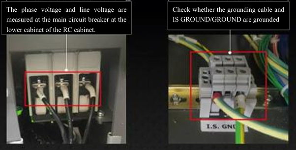
(1) RC control cabinet off the cabinet, the main cut-off switch wiring in, confirm that the grounding cable has been grounded, use a multimeter to measure the power supply voltage, to ensure that the phase voltage is 380V (within ±5% deviation), and the line voltage is 220V (within ±5% deviation) before turning on, the voltage is too large or too small will affect the normal operation of the equipment, and the equipment will be damaged in serious cases.
(2) RC cabinet main circuit breaker closing will be purged, the purging time is about 5 minutes, if the field robot has not been connected to the compressed air will be short-connected to the cabinet purge module in advance, if the compressed air has been connected, no need to short-circuit, the circuit breaker closes directly into the purging.
Purge short connection:
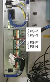
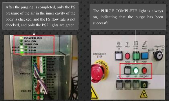
(i) Short-connect the purge inspection cable connector of the purge module. Generally, use 1mm² cables to temporarily shorten them in pairs. When wiring short-connection, be sure to check the wiring. Do not touch the module metal body shell to avoid burning components. The indicator lights on some PS-A, PS-B, FS-A, and FS-B on the module are all displayed in green, proving that the short-connection wiring is correct and wait for the purge to be successful.
(ii) Most on-site robots are 1-to-1 (P250), one control cabinet and one robot body, and there are also 1-to-2 (P250/P500/P700), one main cabinet controls 2 bodies, 1-to-4, etc. (P700). As the body increases, the corresponding purge modules have changed from 1 to multiple blocks. Only when all shorts can they be turned on, and shorts are performed according to the actual situation on site.
(iii) Conditions allow FAC to be used with ready-made short splices and spare parts number EE-6246-644-001 PURGE BOARD JUMPER.
2) Robot boots up
(1) The robot is powered on to show that the purge is complete, and the 'PURGE COMPLETE' indicator is green, press the 'POWER ON' button to power on.
(2) Check whether the screen display of the TP teach pendant is normal, and enter the ALARM page to check whether there is an abnormal alarm.
3) Teaching robot
(1) Make sure that the operation of each axis of the robot body has no interference with the robot cables, paint pipelines or process equipment.
(2) Eliminate abnormal alarms, 50% speed in T1 mode, manually teach the robot each axis to confirm that there is no abnormal noise during operation, and no alarm during operation, etc.
(3) Manually move the robot to a safe position, manually release the brake, and confirm whether the shafts of the brake releaser of the control cabinet are operating normally.
Manual brake release:
(i) Again, make sure that there are no interference objects around the robot, environmental safety, and personnel safety.
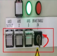
(ii) The control cabinet panel BRAKE RELEASE key switches to the ON state.
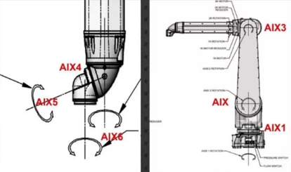
(iii) Press the corresponding button on which axis you need to release, and the arm will slowly descend.
(iiii) The 4.5.6 axes of the wrist are relatively special and belong to the same button as the 1 axis. When releasing the 4.5.6 axes, it is necessary to ensure that the release of the 1 axis is at a safe angle. The wrist axis requires manual rotation by personnel, as it cannot be visually inspected.
6. Work checklist
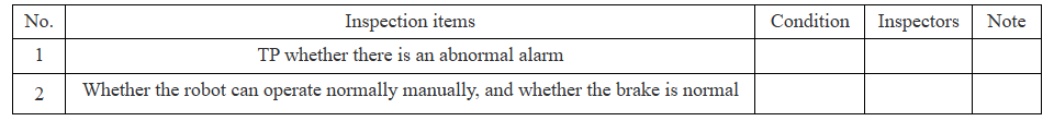
Note: Fill in the condition column with "completed" and "incomplete"; If it is not completed, you can fill in the reason in the remarks column.
———————— END ————————
News
CONTACT US
-
Tel/Wechat/ WhatsApp/Facebook: +86 18740841879
Email: yiliachen@nkfautomation.com
Website: www.nkfautomation.com
Address:No.54,Floor 2,Building 2,No.49,Zijing East Road,High-tech Zone
Chengdu City,Sichuan Province,China


-
Copyright © 2024 Chengdu NKF Intelligent Equipment Co., Ltd. Power by 300.cn


SAF Coolest v1.3.1.2 设置面板 GVVSD-ZTHI-OSZDE-AFW
无数据提示
Sorry,当前栏目正在更新中,敬请期待!
您可以查看其他栏目或返回 首页