

FANUC | Robot Grinding Program Definition
Release time:
2025-07-25 17:16
Source:
FANUC | Robot Grinding Program Definition
1. Definition
In the grinding application field of the robot, although the offline programming of ROBOGUIDE can greatly reduce the workload of grinding and debugging, the on-site debugging after offline programming still needs to be noted, especially the calibration of the user's coordinate system is particularly critical, and the on-site debugging of the grinding program includes program debugging and product verification, product signing, etc., and the whole cycle takes a long time, so it is necessary to reduce the overall debugging time by strictly requiring the accuracy of program debugging.
2. Preparation
(1) Offline programs written by ROBOGUIDE
(2) Familiarize yourself with where the product is placed and where the grinding head is installed
(3) Be clear about the grinding process of the product
3. External conditions
The robot and peripheral auxiliary equipment have been installed in place, water, electricity and gas have been connected, and the products have been adjusted in place.
4. Required skills
Familiar with the basic operations of robots
5. Work steps
1) User coordinate calibration
In order to prevent the grinding head from colliding with the product, the Z value of the offset position register PR[] is reduced before the coordinate calibration, usually its +Z direction is pointing to the product, so Z can be reduced by 20~30mm, for example[0,0,-20,0,0,0]
(1) The X and Y values of the user's coordinates are calibrated, and since the calibration method of the two is the same, the X value calibration is used as an example to illustrate.
Take the square sand grinding head as an example. Usually the value of the user's coordinates is set to (0,0,0,0,0,0,0) when writing offline, of course, it may not be this value, run the square sand grinding program, run to the second point of the program in a single step, and change the X value of the user's coordinates to make the grinding head basically close to the grinding surface of the product, at this time a rough X value is represented by X1. As shown in the figure below, run to both sides of the product along the X direction (because the Z value of the offset position register PR[] has been reduced before, so the robot movement to the other side of the product generally does not interfere), measure the distance of A and B, and measure the user coordinate X value of point A1 by subtracting the user coordinate X value of point A2 when measuring A, and B can be measured in the same way.
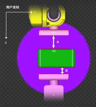
After the A and B values are measured, the X value of the user coordinate will become X2=X1 (A-B)/2, and the above steps will be repeated after changing the user coordinate to X2, and the Xn obtained when the final A and B values are basically the same is the final user coordinate X value.
Note: From point A1 to point A2, you can use the manual method.
(2) Z-value calibration of user coordinates
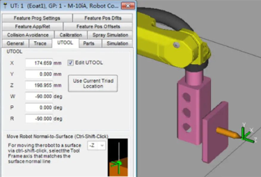
In order to facilitate on-site debugging and obtain a more accurate user coordinate Z value, a sewing needle can be used as an auxiliary tool. Insert the needle tip into the grinding head, and on the real robot (as opposed to the ROBOGUIDE simulated robot), use the 6-point method to position the TCP at the needle tip, ensuring that the Z direction of the TCP points outward from the needle tip as much as possible. The established TCP value should then be input into ROBOGUIDE's UT:1, as shown in the figure below:
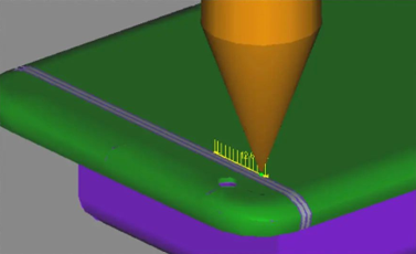
Carry out simple trajectory programming on the upper surface of the product, in this example, the polished product is a mobile phone case, take its back as the upper surface for offline programming, and select a small line on the upper surface of the product for trajectory drawing, as shown in the following figure:
Run the generated program and check that the tip of the needle is just against the back of the product, as shown in the figure below:
Import the above-mentioned generator into the actual robot, run the program in a single step, and the TCP used at the runtime should be the TCP value at the position of the needle tip, in order to prevent the product from colliding with the needle tip, the Z value of the user coordinates can be increased enough in advance, and then slowly adjust the Z value of the user coordinates, and finally make the needle tip just touch the back of the product. The above operations are solely intended to obtain an accurate Z value. Therefore, it is only necessary to adjust the Z value of the user coordinates without altering the X and Y values. Thus, even if the position where the tip of the needle drops is not the position captured in ROBOGUIDE, it does not matter (Ideally, if the X and Y values are adjusted with sufficient accuracy, the drop position of the needle tip should coincide with the position captured in ROBOGUIDE.).
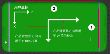
(3) Calibration of W, P, R values for user coordinates
Taking the polishing of mobile phone shell as an example, generally speaking, the W and P values of the user's coordinates affect the grinding effect of the back of the product, and the R value affects the grinding effect of the frame of the product, and the frame is often the place where the grinding requirements are higher and the amount of grinding is most concentrated, so the accuracy of the R value is higher. The calibration of W and P values can be calibrated by borrowing the back of the product, as shown in the figure below, while the calibration of R value, when there are obvious available lines on the back, the lines can be used for calibration, as shown in the white circle 1 in the following figure, and the border can be used to calibrate when there is none, as shown in the white circle 2 in the following figure. Calibration should be performed using user coordinates to move the robot, which can be calibrated using a sharp object tip.
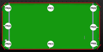
2) Configuration of the offset register
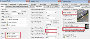
In order to facilitate debugging and improve the controllability of the grinding program, if the same offset register PR[n] is adopted, the phenomenon of "pulling a hair and moving the whole body" often occurs in the debugging process, that is, a slight change in a position will lead to a change in all positions, which is not conducive to debugging, so generally different offset registers PR[] will be used in different grinding sections for segmentation control, as shown in the following figure, different grinding sections of the border adopt different PR[] values. During offline programming, due to the inability to clearly distinguish the positions of each segment on ROBOGUIDE, the same PR[] value is temporarily adopted. During the debugging process, the PR[] values of each segment should be distinguished based on the actual trajectory of the robot.
In order to ensure the grinding effect, the speed of grinding should not be too high, otherwise the grinding requirements cannot be met, and the speed of 50~100 mm is generally required; It is worth noting that the points of the program written offline are generally more (often 1 mm a point), so even if its speed value is large, the robot will not run very fast, because such a dense point has no time to add up the speed.
3) CNT value of the grinding point
When polishing the straight frame of the product, the CNT value can be set to 100, but when polishing the corner, due to the short corner path and high grinding requirements, if the CNT value is too large, part of the trajectory can not be polished, and the CNT value of the corner can be set to about 50, which should not be too small or too large.
6. Precautions
(1) When writing offline programs, the same path, such as the frame of the mobile phone shell (including the long side, corners, short sides) grinding program, should be implemented with a program, and it is not appropriate to divide all kinds of corners into several sub-programs, because there is a characteristic when the robot is running, even if the point is CNT100 when running different programs, there will be a slight pause when switching programs, so that unless a transition point is added at the end of each program, it is very easy to break the product, and if the transition point is added, it will affect the beat.
(2) If the grinding around the corner is not thorough enough, on the one hand, you can slow down the speed, and on the other hand, you can grind back and forth a few more times.
(3) In the grinding process, there are often alarms, emergency stops, etc., at this time, the grinding head should stop vibrating, the water valve should be closed to protect the product, if the customer does not do the corresponding signal control, you can use the background logic to control the grinding head to stop in time.
(4) In the process of debugging, only need to adjust the user coordinates, offset position registers, once the tool coordinates are set, the X, Y, Z values are not allowed to change, and the point data of the program should not be changed, but some points can be shielded.
———————— END ————————
News
CONTACT US
-
Tel/Wechat/ WhatsApp/Facebook: +86 18740841879
Email: yiliachen@nkfautomation.com
Website: www.nkfautomation.com
Address:No.54,Floor 2,Building 2,No.49,Zijing East Road,High-tech Zone
Chengdu City,Sichuan Province,China


-
Copyright © 2024 Chengdu NKF Intelligent Equipment Co., Ltd. Power by 300.cn


SAF Coolest v1.3.1.2 设置面板 GVVSD-ZTHI-OSZDE-AFW
无数据提示
Sorry,当前栏目正在更新中,敬请期待!
您可以查看其他栏目或返回 首页