

Yaskawa Robot | Operation and Programming
Release time:
2025-05-16 16:35
Source:
Yaskawa Robot | Operation and Programming
Yaskawa control box

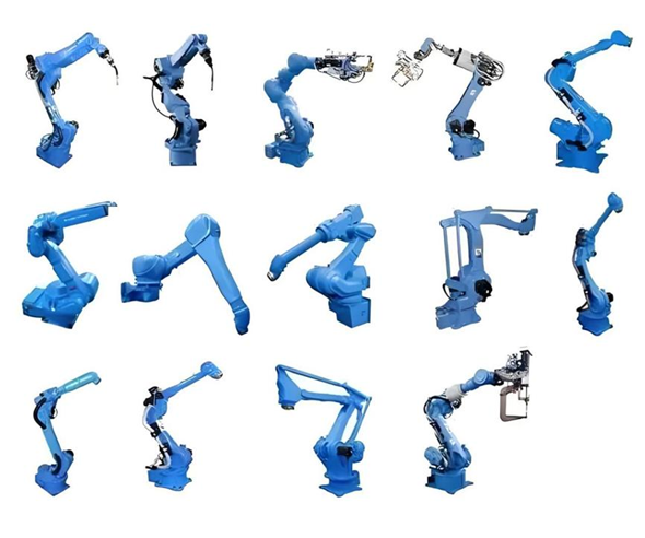
External axis: the body is good for vertical welding, not upward welding, to increase the degree of freedom of the arm, the cost is too high, with an external axis can increase the function.
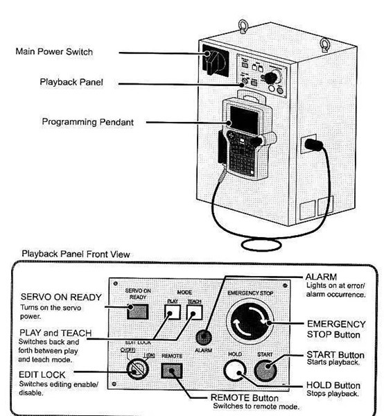
Overview of the XRC control cabinet
The main power switch and door lock are located on the panel of the XRC control cabinet, the teach pendant is hung on the upper right side of the control cabinet, and the reproduction panel is located on the door of the control cabinet, as shown in the figure.
The buttons on the rendition panel are indicated by square brackets and the text in square brackets. For example, [TEACH] indicates the teach-in button on the reproduction panel ![]() .
.
Teach pendant box
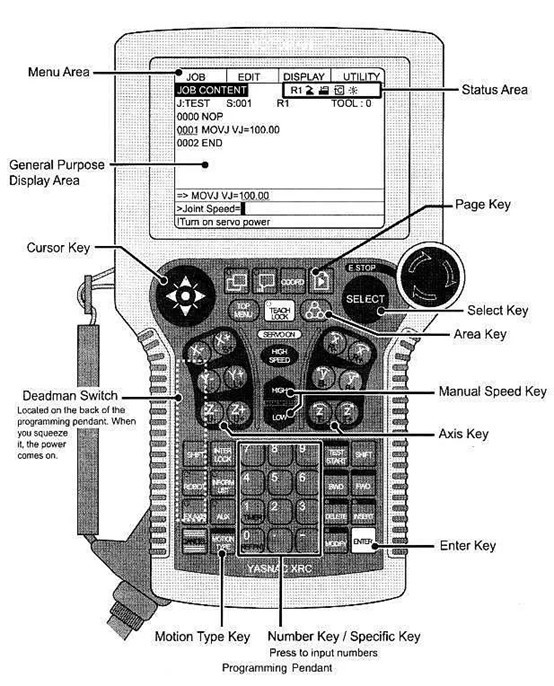
Representation of the key
* Naming key
In this textbook, naming keys are indicated in square brackets and the words in square brackets. For example, [TEACH LOCK] indicates the teach lock key on the teach pendant ![]() . Numeric keys have other functions in addition to numeric functions and have dual function keys. For example,
. Numeric keys have other functions in addition to numeric functions and have dual function keys. For example, ![]() can be expressed as [1] or [TIMER]
can be expressed as [1] or [TIMER]
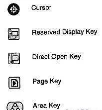
* Symbol key
Symbol keys are not represented by square brackets, but by a small icon.
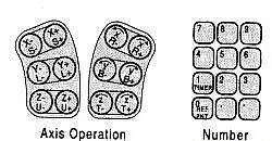
* Axis operation keys and number keys
When all keys are represented at the same time, axis operation keys and number keys are represented by "Axis Operation Keys" and "Number Keys".
* Combination key
Combination keys are represented by connecting them with “+”, for example, [SHIFT]+[COORD].
On-screen instructions
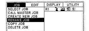
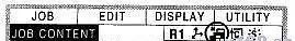
In this textbook, the menu entries in the display area of the teach pendant are represented by {×××}. For example, {JOB} indicates the JOB menu.

The drop-down menus for these menus are represented in the same way.
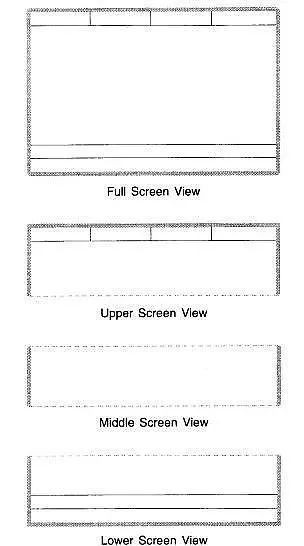
In this textbook, four screen views are used to illustrate the display area of the teach pendant box.
Order of operations
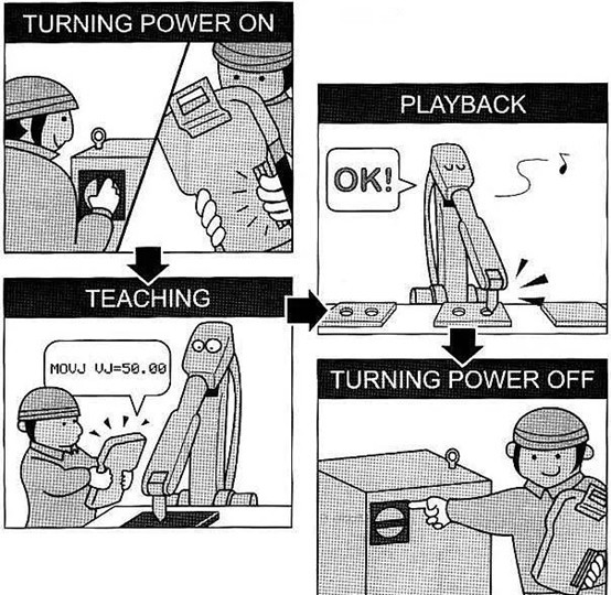
Use the robot in the following order of action:
1) Open the XRC control cabinet;
2) Demonstrate a type of operation for the teaching robot.
3) The robot automatically completes tasks (referred to as 'reproduction');
4) When the job is finished, turn off the power.
Turn on the power
When the power is turned on, always turn on the main power switch first, and then turn on the servo power. When turning on the power, make sure that the area around the robot is safe.
Turn on the mains power
Pull the main power switch to the ON position, turn on the main power, and the system will start to diagnose itself.
* Turn on diagnostics
When the mains power is turned on, the system will self-test and display the opening information on the teach pendant screen.
* After the self-test is completed
The last time the power was turned off, the XRC system saved all status data. After the diagnostics are enabled, the system automatically calls up the job when the machine is stopped. Include:
1. Operating Mode
2. Operational Process
3. The job that was called (if it is in XRC rendition mode, the job is the current job; If it is in XRC teach-in mode, it is the job of this programming)
4. The cursor position of the job
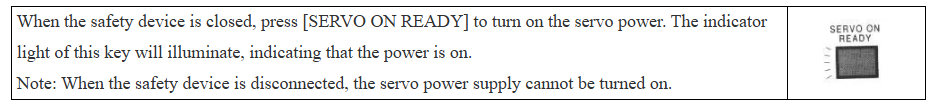
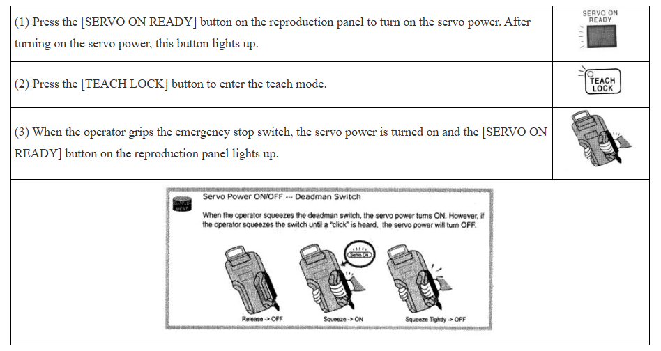
Turn on the servo power
* Reproduction mode
* Teach-in mode
* Coordinate type
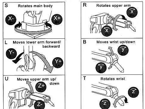
Joint coordinates: Each axis of the manipulator moves independently of each other.
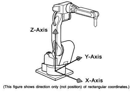
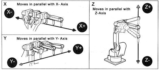
Cartesian coordinates: regardless of the position of the manipulator, it is parallel to any axis of the X-axis, Y-axis, Z-axis.
User coordinates: The manipulator moves parallel to the user's coordinate axis.
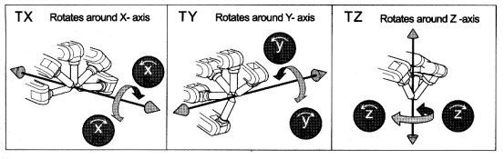
Tool coordinates: In any coordinate system, it is only possible to change the direction of the wrist at the position of the fixed tool center point (TCP).
The movement of the manipulator usually operates the robot with two coordinates: joint coordinates and Cartesian coordinates. Press the coordinate axis operation key on the teach pendant to operate each axis of the manipulator
* Joint coordinates
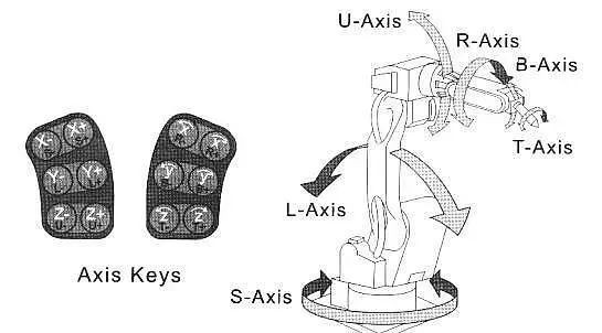
* Cartesian coordinates
* Movement instructions and steps
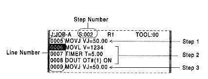
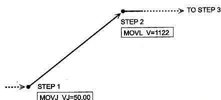
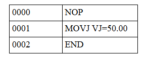
The manipulator uses job instructions to achieve movement and execution reproduction, and these instructions are called motion instructions. Information such as the destination position, the imputation method, the running speed, etc., are recorded in the motion command. The reason why it is called motion command is that the main command starts with "MOV". "MOV" is a "INFORM II." language used in XRC systems. Like what:
MOVJ VJ=50.00MOVL V=1122 PL=1
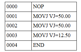
It is a step from one motion command to the next. Step 1 is 001, Step 2 is 002, Step 3 is 003, and so on. The position of step 1 is the position where the motion command with step number 001 (S: 001) is recorded. For example, referring to the content of the following job, when the reproduction is executed, the manipulator moves from step 1 to step 2, and the movement speed is recorded in the motion instruction of step 2. After the manipulator arrives at step 2, the manipulator executes the TIMER command, then executes the DOUT command, and then proceeds to step 3.
Teaching
*Preparation before teaching
The following preparations should be made before teaching:
Press the [REMOTE] button on the reproduction panel to turn off the light, press the [TEACH] button (on the panel), set the teaching mode, press the [TEACH LOCK] button (on the teach box), lock the teaching mode (teach lock, ensure safety), and enter the job name.
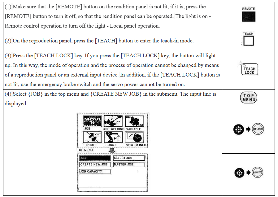
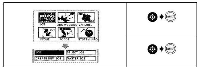
(5) When the new job is displayed, press the [SELECT] key.

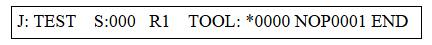
(6) In this example, the name of the job is "TEST", and use the page turn key to display the letter symbol page.
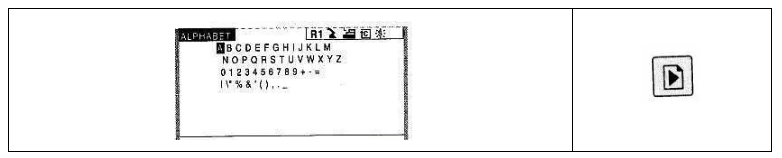
(7) Move the cursor to "T", press the [SELECT] key, "E", "S", and "T", and so on.
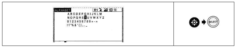
(8) Press [ENTER] to confirm.
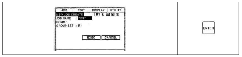
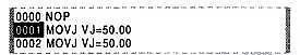
(9) Move the cursor to "EXEC" and press the [SELECT] key, so that the job name "TEST" will be stored in the XRC system, and the job content will be displayed, and the NOP and END commands will be displayed automatically.

Characters that can be used for job names: The job name must consist of numbers, letters, or other characters that have been registered. Between steps 5 and 6, when you press the page turn key, all the characters will be displayed in turn. The name can be represented by 8 digits, letters, and symbols.
* Teaching
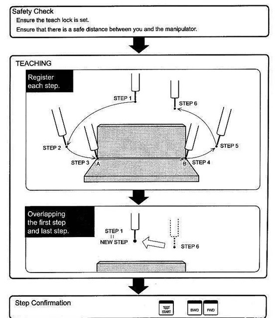
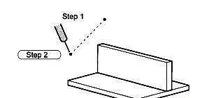
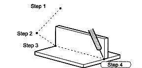
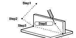
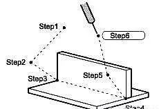
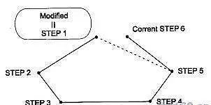
Job teaching: A job is a work program that indicates the task that the manipulator will perform. The program was created using the robotic programming language "INFORM II.". The following example will illustrate how to make a manipulator learn what to do. As shown in the figure below, this example illustrates the steps required to move the robot from point A to point B of the workpiece. It takes a total of 6 steps to complete this job.
path confirmation; so that the first step coincides with the last step; Record each step; Security checks; Ensure that the teach-in mode is locked; Make sure there is a safe distance between you and the manipulator;
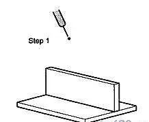
Step 1 – Start Location
Always take care that the manipulator ensures a safe working area before operation.
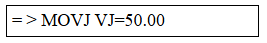
(3) Use the [MOTION TYPE] key to select the joint movement mode so that the joint movement command "MOVJ" is displayed in the input window. 
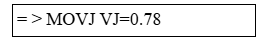
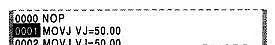
(4) Move the cursor to line 0000 and press the [SELECT] key. 
(5) In the input window, move the cursor to VJ=*.** on the right, which indicates the speed, and then hold down the [SHIFT] key while moving the cursor key up and down (changing the speed of job reproduction) until you get the appropriate speed.
(6) Press the confirmation key [ENTER] to record step 1 (line number 0001).
Step 2 - Adjust the working attitude of the manipulator first near the starting position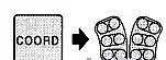
(1) Use the axis operation key to move the robot to a position close to the start of work.
(2) Press the confirmation key [ENTER] to record step 2 (line number 0002).

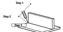
Step 3 - start the position of the operation according to the posture of step 2, move the manipulator to the position of the starting operation.
(1) The [FST] or [SLW] key gives a medium speed, and the speed icon in the status area is displayed in a shape ![]() shape .
shape .

(2) Do not change the posture in step 2, press the [COORD] key to select the Cartesian coordinates, and use the coordinate axis operation key to move the manipulator to the start welding point.
(3) Move the cursor to line number 0002 and press the [SELECT] key.
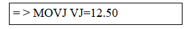
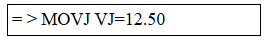
(4) In the input window, move the cursor to VJ=*.** on the right, which indicates the speed, and then hold down the [SHIFT] key while moving the cursor key up and down (changing the speed of job reproduction) until you get the appropriate speed. Set the speed to 12.50%.
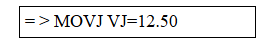
(5) Press the confirmation key [ENTER] to record step 3 (line number 0003).
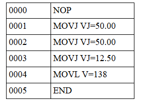
Step 4 - Job End Point: Specify the job end point
(1) Use the axis operation key to move the manipulator to the end point of work.
(2) Press the [MOTION TYPE] key to select a linear motion type (MOVL).

(3) Move the cursor to line number 0003 and press the [SELECT] key.
(4) In the input window, move the cursor to V=*.** on the right, which indicates the speed, and then hold down the [SHIFT] key while moving the cursor key up and down (changing the job reproduction speed) until you get the appropriate speed. Set the speed to 138cm/min.
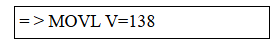
(5) Press the confirmation key [ENTER] to record step 4 (line number 0004).
Step 5 – Leave the workpiece and fixture position: Move the gripper to a position where it will not hit the workpiece or fixture.
(1) Press the [FST] or [SLW] key to change the speed to high speed.
Note: This speed only affects the teach-in speed, which is defined by step 4.
(2) Use the axis operation key to move the robot to a position where it will not hit the fixture.
(3) Press the [MOTION TYPE] button to set the node motion type [MOVJ].
(4) Move the cursor to line number 0004 and press [SELECT].
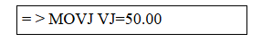
(5) In the input window, move the cursor to VJ=*.** on the right, which indicates the speed, and then hold down the [SHIFT] key while moving the cursor key up and down (changing the speed of job reproduction) until you get the appropriate speed. Here the speed is set to 50%.
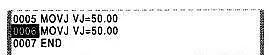
(6) Press the confirmation key [ENTER] to record step 5 (line number 0005).
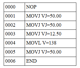
Step 6 – Near the Start Point: Move the robot to the near start point
(1) Use the axis operation key to move the manipulator closer to the start point.
(2) Press the confirmation key [ENTER] to record step 6 (line number 0006).
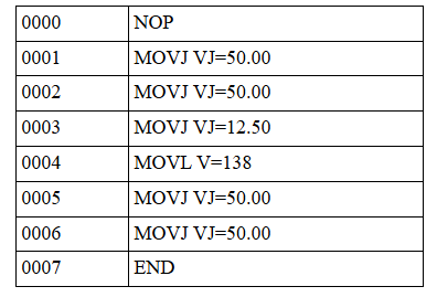
Make sure the first and last steps are consistent: The manipulator stops at step 6, and step 6 must be very close to step 1. It is best to move directly from the end position of step 5 to step 1 so that the manipulator can start the next welding job quickly and efficiently. The following actions will align step 6 (end point) and step 1 (start point).
(1) Move the cursor to step 1 (line number 0001).
(2) Press the [FWD] key and the robot will move to step 1. 
(3) Move the cursor to step 6 (line 0006).
(4) Press the [MODIFY] key. 
(5) Press the confirmation key [ENTER]. This will change the position of Step 6 to be the same as the position of Step 1.
Summary and Improvement
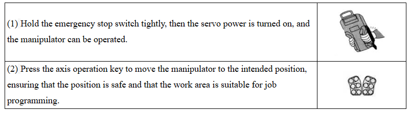
(1) Steps: Hold the switch to turn on the servo power supply → Move to the designated position → Select the form of motion command → Modify the speed → Confirm;
(2) Coordinate type switching [COORD];
(3) Motion command form switching: [MOTION TYPE];
(4) Modify the speed of reproduced motion on any line;
1) Move the cursor to the instruction to modify the line
2) Press [SELECT] to move the line to the input buffer line
3) Move the cursor to VJ=xx.xx and press the [SELECT] key to enter a new speed value or press the [SHIFT] cursor key to modify the speed value
4) [ENTER] key to confirm
(5) Modify the motion command of any line;
1) Move the cursor to the modifier line, and then to the command
2) Press [SELECT]
3) Hold down the SHIFT cursor key to change the motion command
4) [ENTER] key to confirm
* Path confirmation
When the job is programmed, check each step separately to make sure there are no issues.
(1) Move the cursor to step 1 (line 0001).
(2) Press [FST] or [SLW] to change the speed to medium speed.
(3) Press the [FWD] key to confirm each step executed by the manipulator; each time the [FWD] key is pressed, the manipulator will move forward one step.
(4) After gradually completing the path inspection, move the cursor to the beginning of the job (line 0001).
(5) Press and hold the [INTER LOCK] key and the [TEST START] key at the same time to perform all steps consecutively. The manipulator goes through all the steps continuously until the end of the cycle. 
* Modify a job
Note: After modifying the job, you need to reconfirm the route.
Before modifying the job: Confirm the movement of each step of the manipulator. If you need to adjust the job location and add or decrease steps, first display the job content as follows.
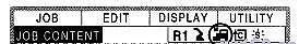
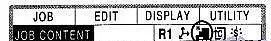
Select {JOB} in the top menu and select the {JOB} item in the submenu. Make sure teach-in mode is turned on.
Change the location data: For example, change the location data in step 2.
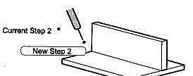
(1) Press the [FWD] key to move the manipulator to step 2 (line 0002);
(2) Use the coordinate axis operation key to move the manipulator to the adjustment position;
(3) Press the [MODIFY] key;
(4) Press the confirmation button [ENTER] to change the position data in step 2.
Add Step: Add a new step between steps 5 and 6.
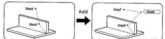
(1) Press the [FWD] key to move the manipulator to step 5 (line 0005);
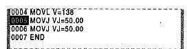
(2) Use the coordinate axis operation key to move the manipulator to the operation position you want to insert;
(3) Press the [INSERT] key; 
(4) Press the confirmation key [ENTER] to insert the step. When the step is added, the number of rows will be adjusted automatically.
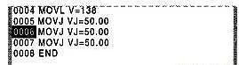
Delete a step: Remove the step that was just added.
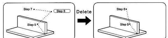
(1) Use the [FWD] key to move the manipulator to step 6 (line 0006);
(2) Make sure the cursor is over the step you want to delete, and then press the [DELETE] key.
(3) Press the OK key [ENTER] to delete this step.
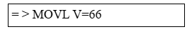
Change the speed between steps: Change the speed of the robot, such as slowing down the speed between steps 3 and 4.
(1) Move the cursor to step 4 (line 0004);
(2) Move the cursor to the command, and then press the [SELECT] key;
(3) In the input window, move the cursor to the right "V=123", which indicates the speed, and then press the [SHIFT] key while moving the cursor key up and down (change the speed of job reproduction) until you get the appropriate speed; The setting speed is 66cm/min;
(4) Press the confirmation key to change the speed.
Disclaimer: All content is for learning and communication only, if testing the application by yourself may lead to unpredictable problems, please test at your own risk and consequences.
———————— END ————————
CONTACT US
-
Tel/Wechat/ WhatsApp/Facebook: +86 18740841879
Email: yiliachen@nkfautomation.com
Website: www.nkfautomation.com
Address:No.54,Floor 2,Building 2,No.49,Zijing East Road,High-tech Zone
Chengdu City,Sichuan Province,China


-
Copyright © 2024 Chengdu NKF Intelligent Equipment Co., Ltd. Power by 300.cn


SAF Coolest v1.3.1.2 设置面板 GVVSD-ZTHI-OSZDE-AFW
无数据提示
Sorry,当前栏目正在更新中,敬请期待!
您可以查看其他栏目或返回 首页