

ABB Robot |12 Steps of Installation and Commissioning
Release time:
2025-06-09 17:12
Source:
ABB Robot | 12 Steps of Installation and Commissioning
The following takes ABB palletizing robot as an example to introduce the 12 steps of installation and commissioning of industrial robots.
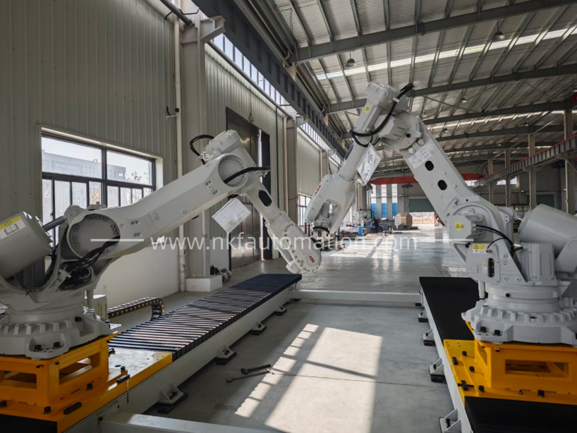
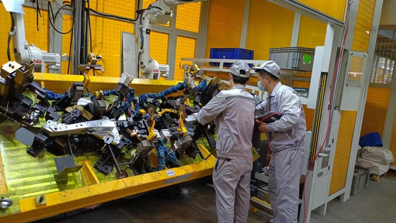
1. Install the robot:
Before installing the robot, the first thing to do is to check whether the equipment is missing parts and observe with your eyes whether the robot is intact. Then install the control cabinet and lift the robot body with a forklift or crane. Finally, the robot body is connected with the control cabinet, and the connection between the robot and the control cabinet is mainly the connection between the motor power cable and the revolution counter cable and the user cable.
2. Set Language:
When the power is turned on for the first time, the default language is English, and you need to change it to the language that needs to be changed to facilitate operation.
(1) Click on the "ABB" icon in the top left corner
(2) Click on "Control Panel"
(3) Click on “language”
(4) Select "Chinese" and click "OK"
(5) Select "Yes" and wait for the bot to restart, and the language setting is complete
3. Backup and Recovery:
Regularly backing up the robot is a good habit to ensure that the robot works properly. The backup file can be placed on the memory inside the robot or backed up to a USB stick.
The backup file contains things like running programs and system configuration parameters. When the robot system fails, you can quickly restore the state before backup through the backup file. Always make a backup before you change the program. It should be noted that the backup recovery data is unique, and the backup data of one robot cannot be restored to another robot.
4. Calibration
Each joint axis of the ABB robot has a position of mechanical origin. In the following cases, it is necessary to update the speed counter at the location of the mechanical origin:
(1) After updating the servo motor revolution counter battery
(2) When the revolution counter fails, after repair
(3) After the number of revolutions counter has been disconnected from the measuring plate
(4) After the power was off, the robot's joint axis moved
(5) When the system alert says "10036 rpm counter is not updating"
5. System I/O configuration and wiring:
It is illustrated by the electrical schematic diagram of the wiring of a gripper.
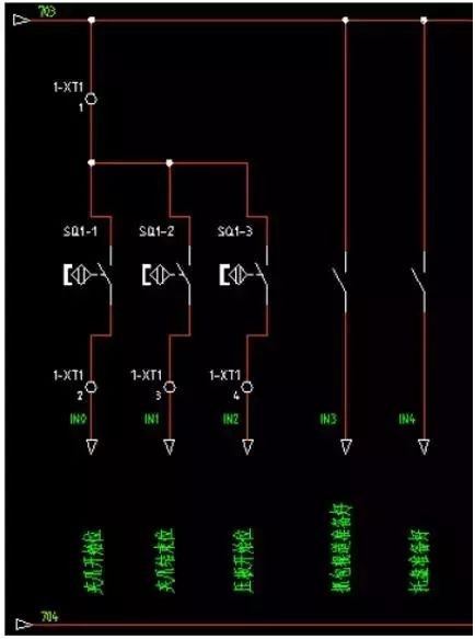
The robot signal input part of the schematic diagram, including 704 bits 24V+, 703 bits 24V-, the input signal by the gripper start bit, the end of the gripper bit, the end of the pressure plate, the grab roller table ready, the pallet ready, a total of five.
The first three are the detection signals of the magnetic switch of the cylinder, and the last two are the signals prepared by the supporting PLC to the robot bags and pallets, in order to achieve electrical isolation, the level signal of the PLC to the robot needs to be converted into the level of the robot itself, which needs to be realized by relays.
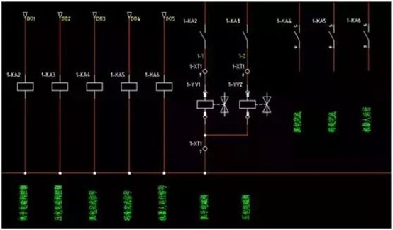
The schematic diagram of the output part is as follows, which are also five outputs, gripper solenoid valve, pressure bale solenoid valve, packet capture completion signal, palletizing completion signal, and robot operation signal.
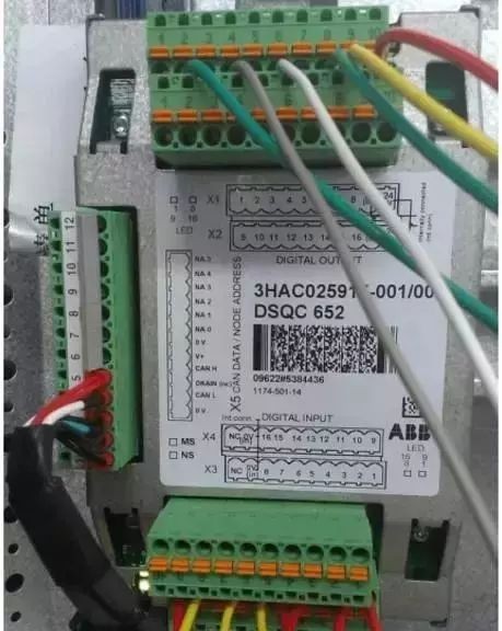
The figure shows the DSQC652 communication board, there are two rows of terminals up and down, including 16 digital inputs and 16 digital outputs, each interface corresponds to an address, for example, X1.1 corresponds to the digital output 0 address (do0), X1.2 uses the digital output No. 1 address (do1), X3.1 corresponds to the digital input No. 0 address (di0), X3.2 corresponds to the No. 1 address of the digital input (di1), and so on. Each terminal strip is connected to 9 to 703 line (COM) and 10 to 704 line (24V).
(1) Configure the I/O unit
1) Click Control Panel
2) Click Configure
3) Click "Theme" and confirm that I/O is selected
4) Select Unit
5) Select 'Show All'
6) Select 'Add'
7) Set the value
8) Click the scroll down arrow
9) Set the address of the DN according to the line
10) Click " OK ", click "Yes"
(2) Set the digital input to di1
1) Select "Signal" in the configuration
2) Select 'Show All'.
3) Select 'Add'.
4) Set the value, click "OK", click "Yes"
Just follow the steps above to change di1 to di0JiaZhuaStart.
After all the signals are configured, connect the corresponding signal lines to the communication board.
In addition, there is a communication method between the robot and the PLC, PROFIBUS.
1) Click on "ABB" on the main touchscreen page
2) Click on "Control Panel"
3) Click on "Configure"
4) Click on "Bus"
5) Click Add to go to the Add page and modify the parameters
6) After returning to the I/O page in step 3, click "Unit Type"
7) Find "DP_INTERNAL_SLAVE_FA" and click to enter
8) After filling in the product ID number, scroll down to find "Input Size" and "Output Size", change them to 64, and click OK. If the pop-up window prompts "Restart immediately", click "No" and wait for the configuration to be completed before restarting.
9) After returning to the I/O page in step 3, click "Unit", create a new "profibus1" unit, and modify the parameters.
10) After returning to the I/O page in the third step, click "Signal" to enter the interface of configuring each I/O signal, the parameter design is basically similar to the previous di1, you only need to change Assigned to Unit to "profibus1".
6. Check the signal:
(1) Click on the "ABB" icon to enter the system menu
(2) Click "Input and Output" to monitor the I/O signals. 0 means no signal, 1 means there is a signal. Check whether the configured signal corresponds correctly to the actual signal.
(3) doGripperA and doGripperB represent two gripper cylinders for the robot, click on one of them.
(4) Then click 0 or 1 to change the fixture status, force the clamp to be loosened and closed, and check whether the solenoid valve wiring is wrong.
7. Import program:
(1) Click on the "ABB" icon, select "Program Editor", click on "Modules"
(2) In the module interface, select "Load Module" to load the program module you need to load from the path where the program module is stored, which is usually stored in the PROGMOD folder and can be opened with Notepad.
8. Workpiece coordinate system setting:
1) The coordinate system of the robot
Setting the coordinates of the workpiece is a prerequisite for teaching, and all teaching points must be established in the corresponding workpiece coordinates. If a teach-in point is set up on WOB J0, if the robot has to be re-taught after moving. If you calibrate on the left side of the corresponding workpiece, you can only change the coordinates of the workpiece without having to reteach all the points.
2) The necessity of setting the coordinates of the workpiece correctly
Inaccurate workpiece coordinates make it difficult for the robot to move in the X/Y direction on the workpiece object.
3) Set the coordinates
(1) Create a WOBJ1 project in the teach pendant
(2) Define the coordinates of the workpiece
(3) Verify the accuracy of the workpiece's coordinates
9. Benchmark point:
(1) Click the "ABB" icon to enter the main system interface, and click "Program Data".
(2) Click on "robtarget"
(3) Select the station to be modified, pPick1 and pPkck2 correspond to the base positions of 1 and 2 stations, respectively.
(4) After clicking on the desk, a drop-down menu will appear, select Edit, and select "Modify Location" in the editing options. Once the modification is complete, the robot will automatically record the new location.
10. Adjust the parameters:
1) Fine-tune the length, width and height of the carton
If there is a slight change in the new carton, which affects the palletizing effect, or the carton packing effect is not very good, it needs to be adjusted.
(1) Click the "ABB" icon to enter the main system interface, and click "Program Data"
(2) Click on "num" to find the three variables "nBoxH", "nBoxW", and "nBoxH", which correspond to the length, width and height of the carton
(3) Click the variable you want to edit and enter a value
(4) After the modifications are completed, click 'OK' and 'Confirm Input'.
2) Modify the number of cartons that have been stacked
This adjustment may be required after the robot has malfunctioned and the cartons have been organized.
(1) Click the "ABB" icon to enter the main system interface, and click "Program Data".
(2) Click "ncount" to enter the array, the component {1} and {2} correspond to the number of 1 station and 2 stations that have been stacked, respectively, click the corresponding value to modify.
3) Fine-tune the gripping position
(1) Click the "ABB" icon to enter the main system interface, and click "Program Data"
(2) Click on "robtarget"
(3) Select the station to be modified, and pPick1 and pPick2 correspond to the basic positions of 1 and 2 stations, respectively
(4) Find the x, y, and z sections to modify them
4) Fine-tune the placement of palletizing
Once each fiducial position has been set, some fine-tuning may be required during the stacking process. Adjustments can only be made in a manual state.
(1) Click the "ABB" icon to enter the main system interface, and click "Program Editor"
(2) Click on "Module" at the top to find the program module where the palletizing address is stored, and click "Show Module" to find the program location of the number of packages that need to be changed.
(3) Select the part that needs to be adjusted, then click "Edit" below, and click the "ABC..." button to enter the change interface.
(4) Type directly on the keyboard and click OK when you're done. After the change, you must pay attention to whether there is a change error, and you must start low-speed debugging and running once before automatic palletizing to ensure safety.
11. Manual debugging:
(1) Leave the No. 4 button on the controller panel to the manual state, which is the middle one gear of the three-speed switch.
(2) Click "ABB" > "Program Editor" to enter the Program Editor
(3) Click on "Move PP to Main"
(4) Reduce the robot speed to a lower speed
(5) Press and hold the enable controller
(6) Press the "Start Button" to start
During commissioning, the robot stops immediately when the controller is released as soon as a problem is found.
12. Automatic Operation:
It can only run automatically after the debugging is completed, and it must be set to a low speed in the early stage.
(1) Toggle the control panel 4 switch to the automatic transmission
(2) One click to confirm, OK (if the speed is 100%, it will only be determined once), be sure to pay attention to the modification of the robot speed, especially in the process of debugging, it is recommended to manually debug the entire palletizing cycle and then operate automatically at a slightly slower speed.
(3) If there is a fault, confirm the fault and fix it
(4) Press the 3 button of the control panel, if it is normal, the white indicator light will light up, and the TP will show that the motor is on.
(5) Press the start button to start the robot, and the robot will continue to follow the program it stopped last time.
(6) If you need to start the program from scratch, you can move the motor "PP to Main" and press the start button again.
(7) Press the pause button to stop the robot from running, at this time the motor is still on, press the start button, the robot will continue to run.
Note: If the motor "PP moves to Main" under pause, the number of stacked and stacked position calculation information will be cleared, and the robot will be re-executed from the main program when it runs again, and the packet number information that has been stacked needs to be re-entered.
Notes:
(1) Before power transmission, make sure that the power supply is wired correctly, firmly and effectively grounded.
(2) The teach pendant should be powered off and plugged out.
(3) Restart after power-off, be sure to wait for about 1 minute after a complete shutdown before starting to prevent data loss.
(4) After making changes to the program content, be sure to review it.
(5) After modifying the palletizing position and parameters, be sure to manually run the program at low speed first, and then run it automatically.
Before making changes, make a backup in time.
After completing all the above steps, you can test the effect through on-site testing, paternity, etc.! If there is a deviation in the test results, you need to find out the cause, you can ask an experienced person to help you check it. After all, the work of robot debugging has a lot to do with the work experience and technical ability of the debugging personnel, let us work together to become a debugging master as soon as possible!
———————— END ————————
News
CONTACT US
-
Tel/Wechat/ WhatsApp/Facebook: +86 18740841879
Email: yiliachen@nkfautomation.com
Website: www.nkfautomation.com
Address:No.54,Floor 2,Building 2,No.49,Zijing East Road,High-tech Zone
Chengdu City,Sichuan Province,China


-
Copyright © 2024 Chengdu NKF Intelligent Equipment Co., Ltd. Power by 300.cn


SAF Coolest v1.3.1.2 设置面板 GVVSD-ZTHI-OSZDE-AFW
无数据提示
Sorry,当前栏目正在更新中,敬请期待!
您可以查看其他栏目或返回 首页